The 1090 Megahertz Riddle (second edition)
Error control in ADS-B
In almost all digital telecommunications, error control is essential. An adequate error control coding scheme in telecommunication allows the receiver to validate the correctness of the information that has been transmitted. Sometimes, it also provides the receiver with the ability to correct errors. Depending on the characteristics of the communication channel and the types of messages, different error control coding schemes can be adopted.
For error detection, three types of error control codes are broadly used, which are 1) parity, 2) checksum, and 3) cyclic redundancy check (CRC)[Grami 2015]. Though there are similarities among these concepts, they should not be confused:
Parity is the simplest form of error detection. Commonly, the message is divided into segments of equal length. One parity bit is added to each segment and sent along with the message. The parity bit ensures either an even or odd number of
1bits are contained in the segment. It guarantees the detection of at least one-bit errors. A two-dimensional parity check is also common, where additional parity bits are added to the same n-th bit in the segments.Checksum bits are longer and computed differently. The message is also first divided into segments of equal length. The checksum is generated by adding the segments using the ones’ complements arithmetic and sent along with the message. On the receiving side, the same arithmetic can be applied, where the complement of the sum should be zero.
CRC is an algorithm based on binary polynomial arithmetic. A pre-defined divisor (also known as ‘generator’) is used to compute the remainder using the binary polynomial division. The CRC remainder is appended to the message. The receiving side can run the same process on the entire message to check whether the remainder is zero. CRC is a much stronger method for error detection. It also offers the ability to correct errors [Mandel and Mache 2009].
Note The CRC remainder term is confusingly defined in Mode S literature and standards. Many documents refer it as parity or checksum. To be consistent with Mode S standards, such as [ICAO 2008; RTCA 2011], parity, checksum, and CRC remainder are considered to be synonyms in this book. They all refer to the CRC remainder.
CRC error control
Mode S communications (including ADS-B) use CRC error control coding. In all types of Mode S downlink messages, the last 24 bits are reserved for the CRC remainder. In ADS-B, the CRC remainder is directly appended as the final 24 bits of the messages. However, in other types of Mode S messages, those bits can be overlaid with other information (such as the ICAO address) using the XOR (exclusive disjunction) operator before being appended to the message.
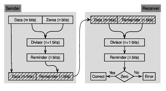
A basic CRC workflow is shown in Figure 1.1. The diagram on the left-hand side shows how the CRC remainder is generated on the sender side. The diagram on the right-hand side shows how the same arithmetic can be used on the receiver side to validate the message.

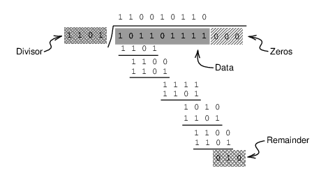
The binary polynomial falls in the finite field arithmetic [Carlitz 1932]. The divisions of binary polynomials can essentially be considered as the XOR bitwise operations, which can be easily implemented and calculated by computers. Figure 1.2 illustrates a CRC remainder calculation example.

ADS-B parity
The polynomial form of the divisor (generator), \(G(x)\), used for ADS-B (as well as other Mode S messages) is [Gertz 1984]:
\[\begin{split} G(x) = &x^{24}+x^{23}+x^{22}+x^{21}+x^{20}+x^{19}+x^{18}+x^{17} \\ &+x^{16}+x^{15}+x^{14}+x^{13}+x^{12}+x^{10}+x^{3}+1 \end{split}\]
This generator code was found by [Kasami and Matoba 1964], which is known for its efficiency to correct burst errors. It can be represented in binary formats as 1111111111111010000001001 (or 1FFF409 in hexadecimal format). A 24-bit CRC remainder is generated using this generator for each ADS-B message.
Knowing the logic of CRC, the computation of the remainder and the verification of the error is fairly simple. Let \(x^{i}\) represent each bit of the message and \(M(x)\) represent the polynomial corresponding to the ADS-B message, the CRC remainder (parity) \(P(x)\) can thus be calculated as:
\[\begin{split} M(x) &= \sum_{i=0}^{87} a_i x^i , \quad a_i \in (0, 1)\\ P(x) &= M(x) ~ \% ~ G(x) \end{split}\]
In the following pseudocode, the algorithm for computing the remainder of an ADS-B message is shown:
generator = 1111111111111010000001001

data_hex = 8D406B902015A678D4D220[000000]  # 11 + 3 zero bytes

data = 1000110101000000011010 1110010000001000000001  # 88 bits
       0101101001100111100011 0101001101001000100000
      [000000000000000000000000]  # append 24 zero bits

FOR i FROM 0 TO (112-24):
  IF data[i] IS 1:
    data[i:i+24] = data[i:i+24] XOR generator

remainder = data[-24:]

# final result: 101010100100101111011010, or AA4BDA in hexadecimal
To check whether an error occurs in the message, replace the data_hex in the previous example with the received message and run the same CRC process. The message is correct if all final 24 remainder bits are zeros.
Try it out Using pyModeS, we can check the correctness of a ADS-B message as:
import pyModeS as pms

msgA = "8D406B902015A678D4D220AA4BDA"
msgB = "8D4CA251204994B1C36E60A5343D"

remainderA = pms.crc(msgA)  # should be 0
remainderB = pms.crc(msgB)  # should be 16
When the remainder is zero, the message is not corrupted. Otherwise, the error has occurred during the transmission.