The 1090 Megahertz Riddle (second edition)
Airborne collision avoidance system
Background
Airborne Collision Avoidance System (ACAS) is a system to reduce the risk of mid-air collisions and near mid-air collisions between aircraft. There are three types of ACAS systems according to [ICAO 2002], which are:
ACAS I: Gives traffic advisories (TA), without recommending manoeuvres.
ACAS II: Gives traffic advisories (TA) and resolution advisories (RA) only in vertical directions.
ACAS III: Gives traffic advisories (TA) and resolution advisories (RA) in both horizontal and vertical directions. ACAS III is not currently implemented
This chapter will focus on ACAS II. The ACAS II is a system that utilizes the aircraft transponder, which interrogates the Mode C and Mode S transponders of nearby aircraft. When threats are detected, corresponding alerts are given to the pilots.
Currently, the most common implementation of ACAS II is Traffic alert and Collision Avoidance System (TCAS) II version 7.1, which was initiated by EUROCONTROL. It has been mandatory for aircraft in Europe since 2015. ACAS II works independently of the navigation system, FMS, and ATC. No input from these systems is considered for producing the alerts.
Note In the future, a new system developed by FAA, called ‘ACAS X’, is expected to replace the current ACAS II. It makes use of dynamic programming to generate resolution advisories and offers four performance capability variants for different air traffic scenarios. [Chomik 2016]
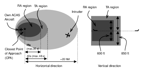
In ACAS II, TA and RA are triggered when certain thresholds to the closest point of approach (CPA) are passed. The thresholds depend on the altitude, speed, and heading of the aircraft. The examples of the TA and RA regions are illustrated in Figure 1.1.
ACAS with Mode C transponders
The ACAS system uses Mode C only all-call interrogation to detect aircraft that are only equipped with Mode A/C transponders. In this case, the ACAS system initiates a sequence of interrogations with increasing power.
The interrogation pulse is slightly different from a Mode A/C-only all-call interrogation. A special \(S_1\) pulse (also known as ‘whisper-shout’) is designed to reduce interference. The \(S_1\) pulse is inserted 2 μs (\(\pm 0.15 \mu s\)) before the \(P_1\) pulse.
The reply should be sent with the following rules:
With both \(S_1\) and \(P_1\) above the minimum triggering level (MTL), no reply will be generated.
With both \(S_1\) and \(P_1\) at MTL, the transponder will respond to 10% of the interrogations.
With \(P_1\) at MTL and \(S_1\) at MTL - 3 dB, the transponder will respond to 70% of the interrogations.
With \(P_1\) at MTL and \(S_1\) at MTL - 6 dB, the transponder will respond to 90% of the interrogations.
ACAS with Mode S transponders
For Mode S transponders, the ACAS system employs a three-phase process, which includes the phases of detection, surveillance, and coordination.
For the detection phase, ACAS passively listens to Mode S only all-call replies (DF=11). These all-call replies are usually generated as a result of ground SSR interrogations, or created by spontaneous acquisition squitter (broadcast of DF=11 message with interrogator code 0). In this process, aircraft with Mode S transponders in the vicinity are discovered. ACAS may also listen to extended squitter messages (Downlink Format 17, ADS-B) to detect other aircraft.
Once another aircraft is determined to be within the ACAS surveillance range, and within 10,000 ft of the own aircraft1, ACAS will initiate a short air-air interrogation (UF=0) to acquire the range. The interrogation rate is defined as:
Once every five cycles: when the target aircraft remains in the surveillance range.
Once every cycle: when the target aircraft is within 3 NM or with time to closest approach less than 60 s.
The surveillance interrogation is stopped when all the following conditions are met:
A reply (DF=0) is received
Both aircraft are below 18,000 ft.
Target aircraft is more than 3 NM and 60 s away from the closest point of approach.
Tables 1.1 and 1.2 lists the fields for ACAS surveillance interrogation and reply messages.
| FIELD | MSG | BITS | |
|---|---|---|---|
| Uplink Format | UF | 1–5 | 5 |
| Reserved | 6–8 | 3 | |
| Reply length | RL | 9 | 1 |
| Reserved | 10–13 | 4 | |
| Acquisition | AQ | 14 | 1 |
| Data selector | DS | 15–22 | 8 |
| Reserved | 23–32 | 10 | |
| Address parity | AP | 33–56 | 24 |
| FIELD | MSG | BITS | |
|---|---|---|---|
| Downlink Format | DF | 1–5 | 5 |
| Vertical status | VS | 6 | 1 |
| Cross-link capability | CC | 7 | 1 |
| Reserved | 8 | 1 | |
| Sensitivity level | SL | 9–11 | 3 |
| Reserved | 12–13 | 2 | |
| Reply information | RI | 14–17 | 4 |
| Reserved | 18–19 | 2 | |
| Altitude code | AC | 20–32 | 13 |
| Address parity | AP | 33–56 | 24 |
Once the target aircraft is within the RA region (a threat), ACAS initiates the coordination interrogation (UF=16). In this step, resolution information are transmitted and received through coordination replies (DF=16). Information that is included in both coordination messages is shown in Tables 1.3 and 1.4.
| FIELD | MSG | BITS | |
|---|---|---|---|
| Uplink Format | UF | 1–5 | 5 |
| Reserved | 6–8 | 3 | |
| Reply length | RL | 9 | 1 |
| Reserved | 10–13 | 4 | |
| Acquisition | AQ | 14 | 1 |
| Reserved | 15–32 | 18 | |
| Message, U | MU | 33–88 | 56 |
| Address parity | AP | 33–56 | 24 |
| FIELD | MSG | BITS | |
|---|---|---|---|
| Downlink Format | DF | 1–5 | 5 |
| Vertical status | VS | 6 | 1 |
| Reserved | 7–8 | 2 | |
| Sensitivity level | SL | 9–11 | 3 |
| Reserved | 12–13 | 2 | |
| Reply information | RI | 14–17 | 4 |
| Reserved | 18–19 | 2 | |
| Altitude code | AC | 20–32 | 13 |
| Message, V | MV | 33–88 | 56 |
| Address parity | AP | 89–112 | 24 |
Specific fields in the above mentioned messages are defined as follows:
Reply length (RL): 1 bit, it defines the required reply format:
0requires a reply with DF=0, while1requires reply with DF=16.Acquisition (AQ): 1 bit, it contains code that controls the content of RI field in the reply.
Data selector (DS): 8 bits, it indicates the BDS code of the MV content in reply with DF=16.
Vertical status (VS): 1 bit, it indicates whether the aircraft is airborne (
0) or on the ground (1).Cross-link capability (CC): 1 bit, it refers to the capability of reply DF=16 upon request of UF=0. When this 1-bit field is set to
1, the cross-link is supported. Otherwise, the field is set to0.Sensitivity level (SL): 3 bits, it represents the sensitivity level of the ACAS system, except that
0indicates the ACAS is inoperative.Reply information (RI): 4 bits, it indicates the type of reply to interrogating aircraft. For ACAS message, valid values are 0 and from 2 to 4. Other values are not part of the ACAS:
0000: No operating ACAS
0010: ACAS with resolution capability inhibited
0011: ACAS with vertical-only resolution capability
0111: ACAS with vertical and horizontal resolution capabilityAltitude Code (AC): 13 bits, it encodes the altitude of the aircraft. It can be decoded according to section [sec:alt_code].
ACAS coordination interrogation
Message U-definition (MU) is transmitted in ACAS coordination interrogation. MU is used to transit resolution, ACAS broadcast, and RA broadcast.
UDS=3,0
When ACAS resolution information is transmitted in the UF=16 message, the first 8 bits of MU, U-definition subfields (UDS), are set to 0011 0000 (UDS=3,0). The corresponding fields are indicated in Table 1.5.
| FIELD | MSG | MU | BITS | |
|---|---|---|---|---|
| U-definition subfield 1 [0011] | UDS1 | 33–36 | 1–4 | 4 |
| U-definition subfield 2 [0000] | UDS2 | 37–40 | 5–8 | 4 |
| Reserved | 41 | 9 | 1 | |
| Multiple threat bit | MTB | 42 | 10 | 1 |
| Cancel vertical RAC | CVC | 43–44 | 11–12 | 2 |
| Vertical RAC | VRC | 45–46 | 13–14 | 2 |
| Cancel Horizontal RAC | CHC | 47–49 | 15–17 | 3 |
| Horizontal RAC | HRC | 50–52 | 18–20 | 3 |
| Reserved | 53–55 | 21–23 | 3 | |
| Horizontal sense bits | HSB | 56–60 | 24–28 | 5 |
| Vertical sense bits | VSB | 61–64 | 29–32 | 4 |
| Aircraft address | MID | 65–88 | 33–56 | 24 |
These fields can be interpreted as follows:
Multiple threat bit (MTB): 1 bit, indicates whether multiple threats are present.
Vertical RAC 2 (VRC): 2 bits, contains vertical resolution advisory complement information:
00: No vertical RAC information
01: Do not pass below
10: Do not pass above
11: Not assignedCancel vertical RAC (CVC): 2 bits, cancels previously sent VRC:
00: No cancellation information
01: Cancel "Do not pass below"
10: Cancel "Do not pass above"
11: Not assignedHorizontal RAC (HRC): 3 bits, contains horizontal resolution advisory complementary information:
000: No information
001: Other ACAS sense is turn left; do not turn left
010: Other ACAS sense is turn left; do not turn right
101: Other ACAS sense is turn right; do not turn left
110: Other ACAS sense is turn right; do not turn right
other: Not assignedCancel horizontal RAC (CHC): 3 bits, cancels previously sent HRC:
000: No cancellation information
001: Cancel "Do not turn left"
010: Cancel "Do not turn right"
other: Not assignedHorizontal sense bits (HSB): 5 bits, uses Hamming code with an extra parity bit to detect errors (up to 3 bits) in CHC and HRC fields.
Vertical sense bits (VSB): 4 bits, uses Hamming code with an extra parity bit to detect errors (up to 3 bits) in CVC and VRC fields.
Aircraft address (MID): 24 bits, contains the 24-bits aircraft transponder address of the interrogating ACAS aircraft.
UDS=3,1
When UF=16 is used for RA broadcast, UDS is set to 0011 0001 (UDS=3,1). The corresponding fields are described in Table 1.6.
| FIELD | MSG | MU | BITS | |
|---|---|---|---|---|
| U-definition subfield 1 [0011] | UDS1 | 33–36 | 1–4 | 4 |
| U-definition subfield 2 [0001] | UDS2 | 37–40 | 5–8 | 4 |
| Active RAs | ARA | 41–54 | 9–22 | 14 |
| RAC’s record | RAC | 55–58 | 23–26 | 4 |
| RA terminated indicator | RAT | 59 | 27 | 1 |
| Multiple threat encounter | MTE | 60 | 28 | 1 |
| Reserved | 61–62 | 29–30 | 2 | |
| Mode A identity code | AID | 63–75 | 31–43 | 13 |
| Mode C altitude code | CAC | 76–88 | 44–56 | 13 |
These fields can be interpreted as follows:
Active RA (ARA): 14 bits, indicates the resolution advisory characteristics. It has to be interpreted together with the MTB field.
When ARA first bit (MSG bit 41) is
1and MTE is either0or1:Bit 42: RA is corrective (
1) or preventive (0)
Bit 43: RA is downward sense (1) or upward sense (0)
Bit 44: RA is increased rate (1) or not (0)
Bit 45: RA is a sense reversal (1) or not (0)
Bit 46: RA is altitude crossing (1) or not (0)
Bit 47: RA is positive (1) or vertical speed limit (0)
Bit 48–54: Reserved for ACAS IIIWhen ARA first bit (MSG bit 41) is
0and MTE is1:Bit 42: RA requires a correction in the upward sense (
1) or not (0)
Bit 43: RA requires a positive climb (1) or not (0)
Bit 44: RA requires a correction in the downward sense (1) or not (0)
Bit 45: RA requires a positive descent (1) or not (0)
Bit 46: RA requires a crossing (1) or not (0)
Bit 47: RA is a sense reversal (1) or not (0)
Bit 48–54: Reserved for ACAS IIIWhen ARA first bit (MSG bit 41) is
0and MTE is0, no vertical RA is generated.
RAC’s record (RAC): 4 bits, contains current active RACs that are received from other ACAS aircraft (if any). Each of the four bits in this field indicates the following RAC when set to
1. When a bit is set to0, the corresponding RAC is inactive.Bit 55: Do not pass below
Bit 56: Do not pass above
Bit 57: Do not pass left
Bit 58: Do not pass rightRA terminated indicator (RAT): 1 bit, indicates whether ACAS is currently generating RA in the ARA field or RA in the ARA field has been terminated.3
Multiple threat encounter (MTE): 1 bit, indicates whether multiple threats are currently being processed by the ACAS resolution. When MTE is set to
0, either one threat is being processed (ARA bit 41 sets to1) or no threat is being processed (ARA bit 41 sets to0). When MTE is set to1, multiple threats are being processed.Mode A identity code (AID): 13 bits, contains the Mode A identity code (sqwake code) of the reporting aircraft. It can be decoded according to section [sec:id_code].
Mode C altitude code (CAC): 13 bits, contains the Mode C altitude code reporting aircraft. It can be decoded according to section [sec:alt_code].
UDS=3,2
When UF=16 is used for ACAS broadcast, UDS is set to 0011 0010 (UDS=3,2). The corresponding fields are indicated in Table 1.7.
| FIELD | MSG | MU | BITS | |
|---|---|---|---|---|
| U-definition subfield 1 [0011] | UDS1 | 33–36 | 1–4 | 4 |
| U-definition subfield 2 [0010] | UDS2 | 37–40 | 5–8 | 4 |
| Reserved | 41–64 | 9–32 | 24 | |
| Aircraft address | MID | 65–8 | 33–56 | 24 |
The only information that is broadcast in the MU of this message is the 24-bit transponder address of the interrogating aircraft. Its purpose is to inform other aircraft about ACAS capability of the broadcasting aircraft.
ACAS coordination reply
Message V-definition (MV) is transmitted in ACAS coordination reply message.
VDS=3,0
Similar to MU in the UF=16 message, MV in the DF=16 message contains a few common fields. The corresponding fields are indicated in Table 1.8.
| FIELD | MSG | MV | BITS | |
|---|---|---|---|---|
| V-definition subfield 1 [0011] | VDS1 | 33–36 | 1–4 | 4 |
| V-definition subfield 2 [0000] | VDS2 | 37–40 | 5–8 | 4 |
| Active RAs | ARA | 41–54 | 9–22 | 14 |
| RAC’s record | RAC | 55–58 | 23–26 | 4 |
| RA terminated indicator | RAT | 59 | 27 | 1 |
| Multiple threat encounter | MTE | 60 | 28 | 1 |
| Reserved | 61–88 | 29–56 | 28 |
We can see that the structure of the MV fields is similar to MU fields of RA broadcast (UDS=3,1) from Table 1.6. The interpretations of these fields are also the same as in section 1.4.2.
Other VDS
When the first eight bits are not 0011 0000, the MV field contain the Ground-initiated Comm-B information that was requested in DS field of uplink (UF=0) in Table 1.1. Comm-B will be explained in the next chapter.